
In high-frequency radar transmitter and receiver (T/R) architecture, the key variance in Coaxial vs Drop-in Isolator devices resides in mechanical interconnection, electromagnetic containment, and thermal dissipation paths. A Coaxial Isolator features dedicated RF connector types (e.g., SMA, N-Type, or TNC), enclosed in a pre-tuned Faraday housing suited for modular, test-bench, or high-power chassis installations.
Conversely, a Drop-in Isolator utilizes planar contact tabs engineered for direct soldering onto printed microstrip or stripline transmission paths on high-frequency substrate layers (e.g., Rogers, Taconic). While drop-in units dramatically reduce form factor (SWaP-C) in Active Electronically Scanned Arrays (AESA), coaxial units offer plug-and-play assembly, higher mechanical isolation, and superior field serviceability in bulky military pulse radar cabinets.
⚒ Structural Architecture & Signal Isolation Flow
How non-reciprocal ferrite junctions safeguard radar solid-state power amplifiers (SSPA) and gallium nitride (GaN) high-power amplifiers (HPA) from reflected antenna power.
Figure 1: Non-reciprocal ferrite disk under static magnetic bias channels forward wave (Port 1 → Port 2) with minimal attenuation while dumping reverse wave (Port 2 → Port 3) into an internal RF termination resistor to prevent amplifier burnout.
☰ Coaxial vs Drop-in Isolator: Parametric Comparison Matrix
Examine core electrical, mechanical, and thermal parameters critical for evaluating Coaxial vs Drop-in Isolator implementations in modern radar circuit designs.
| Technical Parameter | Coaxial Isolator Solution | Drop-in Isolator Solution |
|---|---|---|
🔌 Mechanical Interface |
Interconnects via calibrated Connector Types (SMA, N-Type, TNC, 2.92mm). Self-contained housing mounted using external chassis screws. | Features flat gold/silver tab leads soldered directly to Microstrip or coplanar lines on high-frequency substrate layers. |
📏 Footprint & SWaP Impact |
Larger volume due to external coaxial connector bodies and robust aluminum shielding. Moderate to heavy mass profile. | Minimal volume; sits directly recessed inside machined carrier cavity pockets on RF motherboards. Ideal for ultracompact SWaP. |
📡 Frequency Coverage & Bandwidth |
Extremely wide frequency range down to HF/VHF (e.g., 34 MHz) up to Ka-band. Wide octave and multi-octave bandwidth designs. | Optimized for narrow to moderate percentage bandwidth (5% to 40%). Superior up through C, X, Ku, and millimeter-wave radar bands. |
🌡 Thermal Dissipation |
Heat dissipates through external connector shells and external chassis mounting flanged heatsinks. | Direct bottom-flange thermal conduction to ground plane/liquid cold plates; handles high continuous-wave (CW) & peak power. |
🔬 Substrate Integration |
External to PCB. Requires RF cables, semi-rigid assemblies, or hermetic coaxial feedthrough transitions. | Seamless integration onto Substrate boards (Rogers RT/duroid, Taconic, PTFE) without coax line transitions. |
⚙ Assembly & Reworkability |
Simple torque wrench connection. Fast plug-and-play assembly, zero solder risk, effortless field diagnostics. | Requires skilled micro-soldering, gap height matching, reflow control, and precise dielectric constant compensation. |
💲 Manufacturing & BoM Cost |
Higher unit cost due to precision precision-machined RF connector types, internal transition pins, and factory calibration. | Lower per-unit component BoM cost; however, demands higher precision PCB routing and tighter machining tolerances. |
🔍 Coaxial vs Drop-in Isolator: In-Depth Engineering Evaluation
Navigating the hardware trade-offs across insertion loss, RF parasitic reactance, transmission stability, and structural durability.
1. Mounting Method & Interconnect Discontinuity
When choosing between Coaxial vs Drop-in Isolator modules, interface parasitics represent a vital differentiation point. Coaxial isolators rely on precision-machined 50-ohm interfaces such as SMA or N-type connectors. These connectors feature rigid pin contacts that join the external coaxial transmission cable to internal ferrite junction striplines. The connection is mechanically independent of the system circuit board.
Drop-in isolators, in contrast, are dropped into milled cutouts within metal baseplates. Their thin, flexible copper or gold-plated tabs are micro-soldered directly across the Microstrip line printed on high-frequency microwave Substrate materials (such as Rogers RO4350B or RT5880). This eliminates cable run insertion loss and connector bulk, but introduces capacitance/inductance steps that must be tuned through matching stubs or tab height control.
2. Footprint Constraints in AESA Radar (SWaP-C)
Size, Weight, Power, and Cost (SWaP-C) represent the primary driving metrics in contemporary Active Electronically Scanned Array (AESA) radar designs. In these systems, hundreds or thousands of T/R channels are arranged within a half-wavelength lattice spacing (λ/2) to eliminate grating lobes during wide beam steering.
A standard coaxial isolator adds significant length and weight due to its threaded connector shells and thick alloy walls. This bulk is unacceptable inside tightly packed multichannel AESA radar tiles. In the Coaxial vs Drop-in Isolator selection process, drop-in versions win decisively for compact multi-channel radar modules, allowing designers to embed magnetic protection inside ultra-shallow modular housings without external cabling.
3. RF Spectrum Coverage, Bandwidth & Return Loss
The operating RF Spectrum profoundly influences component choice. In VHF, UHF, and lower L-band surveillance radar (e.g., 34 MHz to 1.5 GHz), physical ferrite and magnetic circuit sizes are fundamentally massive. At these low frequencies, coaxial packaging is typically mandatory because stripline structures would consume too much valuable PCB real estate.
However, across S-band, C-band, X-band (8.0–12.0 GHz), and Ku-band tracking radar regimes, the ferrite puck dimensions scale down dramatically. Drop-in isolators deliver moderate-to-wide fractional Bandwidth (upwards of 20% to 40%) with insertion losses below 0.30 dB. Because drop-in components remove the return loss degrades caused by dual SMA adapters, system-level VSWR is maintained with high consistency over temperature extremes.
4. Thermal Dissipation & High-Power Radar Pulses
Radar systems operate with high peak-to-average power ratios (PAPR) during transmitter pulse bursts. When an antenna mismatch occurs (due to radome ice, structural damage, or beam scanning reflections), substantial reflected power is redirected into the isolator's internal termination resistor.
In a Coaxial vs Drop-in Isolator thermal comparison, drop-in isolators offer a shorter conductive path to external heatsinks. Bolted directly onto nickel-plated aluminum or copper-molybdenum cold plates via high thermal-conductivity interface materials, drop-in units can dissipate continuous reflected loads exceeding 100W to 250W. Coaxial isolators rely largely on conduction through outer connector barrels or auxiliary chassis flanges, which can induce thermal throttling in dense environments.
✅ Radar Application Matrix: Coaxial vs Drop-in Isolator
Guidelines from microwave systems engineers for selecting the proper isolator topology based on operational deployment environments.
When to Specify Coaxial Isolators
Recommended Radar Architectures: Large-scale ground-based primary surveillance radar, high-power marine navigation radar, RF testing fixtures, lab prototyping, and rack-mounted transmitter units.
- Modular Field Replacement: When radar subsystems must be repaired or replaced rapidly at sea or in distant depots without board-level desoldering.
- Thick Coaxial Line Routing: When joining high-power travelling wave tubes (TWT) or solid-state drivers using N-type or 7/16 DIN rigid coax lines.
- Vibration and Shock Environments: In rugged mechanical chassis where connectorized cables with safety lock wire provide dependable mechanical decoupling from board shock.
- Broadband Legacy Platforms: Systems requiring multi-octave performance where the isolator is shared across multiple bands.
When to Specify Drop-in Isolators
Recommended Radar Architectures: Modern AESA (Active Electronically Scanned Array) radar, airborne fire-control radar, missile seeker heads, synthetic aperture radar (SAR), and compact marine radar transceivers.
- Direct Planar Board Integration: When mating directly to thin microwave Substrate boards via low-loss Microstrip gold ribbons.
- Strict Weight & Spatial Limits: Where every gram and cubic millimeter impacts payload range, aerodynamic envelope, or drone flight time.
- Liquid-Cooled Cold Plate Designs: When the isolator baseplate can be clamped with thermal paste or phase change materials straight to cold plates.
- High-Volume SMT Production: When production volume allows automated pick-and-place and reflow or precision inductive soldering workflows.
🔬 RF & Microwave Isolators, Circulators & Passive Components
Explore our factory-engineered standard and custom microwave products engineered for aerospace, radar, defense, and high-frequency communication systems.
-
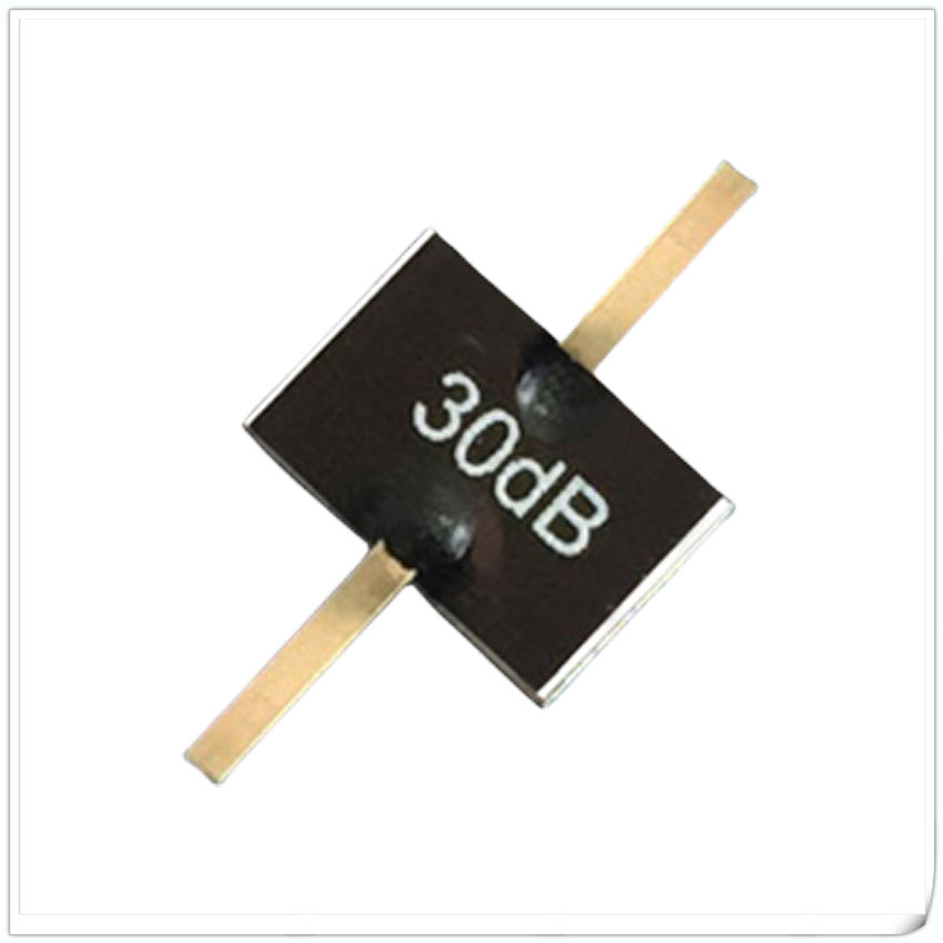
Leaded Attenuator
Data Sheet Power Freq. Range (GHz) Dimension(mm) Attenuation Value (dB) Substrate Material Configuration Data Sheet (PDF) A B H G L W 5W 3GHz 4.0 4.0 1.0 1.8 3.0 1.0 ...
View Specifications → -

Flanged Attenuator
Data Sheet Power Freq. Range GHz Dimension(mm) Attenuation Value (dB) Substrate Material Configuration Data Sheet (PDF) A B C D E H G L W Φ 5W DC-3.0 13.0 4.0 9.0 4.0 0.8 1...
View Specifications → -

TG3234BS 2.0 to 4.0GHz Coaxial Isolator
2.0 to 4.0GHz Coaxial Isolator Order Examples 2.0 to 4.0GHz Coaxial Isolator Connector Type 2.0 to 4.0GHz Coaxial Isolator Basic Specifications 2.0 to 4.0GHz Coaxial Isolator Specificatio...
View Specifications → -
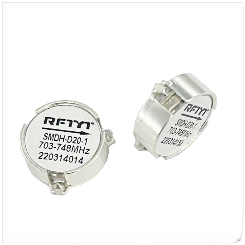
SMT Circulator
Data Sheet RFTYT 400MHz-9.5GHz RF Surface Mount Circulator Model Freq.Range BandWidth Max. IL. (dB) Isolation (dB) VSWR Forward Power (W) Dimension (mm) PDF SMTH-D35 300-1000MHz 1...
View Specifications → -

Drop in Isolator
Data Sheet RFTYT 34MHz-31.0GHz RF Drop in Isolator Model Frequency Range (MHz) Bandwidth (Max) Insertion Loss (dB) Isolation (dB) VSWR (Max) Forward Power (W) Reverse Power (W) Dimens...
View Specifications → -

Chip Attenuator
Data Sheet Power (W) Frequency Range (GHz) Dimension(mm) Substrat Material Configuration Attenuation Value (dB) Data Sheet (PDF) L W H 10 DC-3.0 5.0 2.5 0.64 AlN FIG ...
View Specifications → -

Dual Junction Circulator
Data Sheet RFTYT 450MHz-12.0GHz RF Dual Junction Coaxial Circulator Model Frequency Range B.W/Max Forard Power (W) Dimension W×L×Hmm SMA Type N Type THH12060E 80-230MHz 30% 150 12...
View Specifications → -

RFT50-10WT0404 DC-8.0GHz Chip Termination
Outline Drawing (Unit: mm/inch) Dimensional tolerance: 5% unless otherwise stated Typical Performance: Installation method Power De-rating Reflow time and temperature diagram P/N Designation M...
View Specifications → -

WH3234B 2.0 to 4.2GHz Drop in Circulator
Order Examples Basic Specifications Specifications Model No (X=1: →Clockwise) (X=2: ←Anticlockwise) Freq. Range GHz Insertion Loss dB (max) Isolation dB (min) VSWR (max) Power W W...
View Specifications → -

RFT50N-10CT2550 DC~6.0GHz Chip Termination
Typical Performance: Installation method Power De-rating Reflow time and temperature diagram: P/N Designation Reflow time and temperature diagram ■ After the storage period of newly purchased pa...
View Specifications → -

1-DUP-136M143-02N RF Duplexer
Model DUP-136M143-02N Frequency Rx 136~138MHz Tx 143~145MHz Insertion Loss Rx ≤1.5dB Tx ≤1.5dB Ripple Rx ≤0.8dB Tx ≤0.8dB Return Loss Rx ≥18 dB Tx ≥18 dB Rejection Rx ≥70dB...
View Specifications → -

3-PD06-F8318-S/500-8000MHz 500-8000 MHz RF Power Divider
Model PD06-F8318-S/500-8000MHz Frequency Range 500-8000 MHz Insertion Loss ≤3.5dB Isolation 16 dB Min VSWR Input: 1.80 Max Output: 1.50 Max Amplitude Unbalance ±0.1 dB Phase Unbalanc...
View Specifications →
❓ Frequently Asked Engineering Questions (FAQ)
Direct answers to common technical queries on Coaxial vs Drop-in Isolator selection in radar RF front-ends.
Request Custom OEM/ODM Isolator Parameter Drawings
Collaborate directly with our microwave engineering staff. Whether you need custom mechanical housings, specific connector configurations (SMA, N-Type, SMP, 2.92mm), customized tab alignments, or wideband dual-junction architectures for your radar platform, our engineering team is here to assist.


